2. Photon-HDF5 format definition
2.1. Overview
A Photon-HDF5 is a HDF5 file with a predefined structure for timestamp-based data.
A screen-shot of a typical Photon-HDF5 file opened in HDFView is shown here:
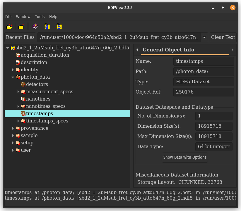
The previous figure shows the 5 main groups contained in a Photon-HDF5 file. Of these, /photon_data/ and /setup/ contains the raw data and all the information needed for the analysis. A schematic overview is shown in the next figure:
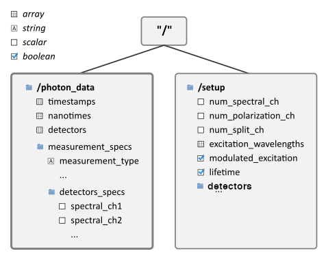
The remaining 3 groups provide additional metadata not necessary for data analysis:
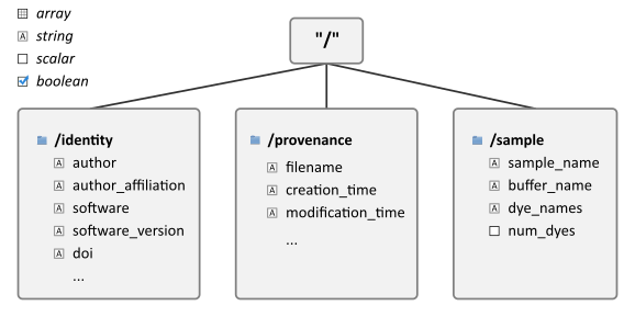
A brief description of these 3 metadata groups follows:
/identity/: Information about the data file.
/provenance/: Information about the original data file (when the Photon-HDF5 file has been converted from another format).
/sample/: Description of the measured sample.
Finally, the group /user/ may be included to store
additional data not defined in the Photon-HDF5 spec.
Unlike all other groups, the contents of the /user/ group are not
rigidly defined. However, guidelines are provided for how data should
be stored and what should be included.
Note
Since the format of the /user/ group is not rigid, it will be ignored by official readers.
2.2. Root-level parameters
The root node (“/”) in a Photon-HDF5 file contains the following fields:
/acquisition_duration: (float) the measurement duration in seconds.
/description: (string) a user-defined measurement description.
In addition, the root node has the following attributes which distinguish a Photon-HDF5 file from other HDF5 files:
/format_name: (string) must contain the string “Photon-HDF5”
/format_version: (string) the Photon-HDF5 format version.
2.3. Photon-data group
This section describes the layout and fields in the /photon_data/ group.
Note that only the kind of data is specified (i.e. scalar (float or integer),
integer array, float array), but no data type size is mandated.
For arrays, the most commonly used data-type is indicated.
Note
In multi-spot measurements each spot is represented in a separate group
named sequentially photon_data0, photon_data1 …
See Multi-spot measurements for more details.
Mandatory fields:
timestamps: (integer array) photon timestamps. Typical data-type int64.
- timestamps_specs/
timestamps_unit: (float) timestamp units in seconds.
Optional if there is only 1 detector, otherwise mandatory:
detectors: (integer array) detector IDs for each timestamp. Must be the same length as
timestamps. Typical data-type uint8.
When the dataset contains TCSPC or nanotime information (i.e. arrival time of each photon with respect to a laser pulse), the following fields must be present:
nanotimes: (integer array) TCSPC nanotimes. Conventionally the time axis direction is the “natural” direction, i.e. lifetime decays look correctly oriented in time. Must be the same length as
timestampsFor more details see Nanotimes time direction. Typical data-type uint16.- nanotimes_specs/
tcspc_unit: (float) TAC/TDC bin size (in seconds). In official photon-HDF5 readers, this field is used for determining resolution of nanotimes. Other fields in
nanotimes_specsare ignored if not needed.tcspc_num_bins: (integer) number of TAC/TDC bins.
tcspc_range:(float) (Optional) full-scale range of the TAC/TDC (in seconds). This a derived field equal to
tcspc_unit * tcspc_num_bins.
Note
In the unusual case where detectors in a single spot do not share the same
settings, then nanotimes_specs should be omitted and the data
exclusively stored in the equivalent fields in /setup/detectors/ where
per-detector settings can be stored. Doing so will mean readers of <v0.5 will
not be able to read the file.
Finally, if the data come from a simulation, /photon_data/ may contain:
particles: (integer array) a particle ID (integer) for each timestamp. Typical data-type uint8.
2.3.1. Measurement specs
The group /photon_data/measurement_specs/ group contains additional
information allowing inference regarding the interpretation of the data
for each specific type of measurement.
measurement_type: (string) the type of the measurements. Valid names are:
“generic” a generic measurement defined by fields in
/setupandmeasurement_specs.“smFRET” (1 excitation wavelengths, 2 detection spectral bands). If
/setup/lifetimeis True the measurement also includes TCSPC nanotimes.“smFRET-usALEX” (2 excitation wavelengths, 2 detection colors)
“smFRET-usALEX-3c” (3 excitation wavelengths, 3 detection colors)
“smFRET-nsALEX” (2 pulsed-laser wavelengths, 2 detection colors)
The measurement_type field describes the type of measurement
saved within the file. A “specific” measurement type can mandate
the presence of certain fields in measurement_specs/ and certain
fields match particular values in /setup/
(see also Measurement type).
In Photon-HDF5 <0.5, each type of measurement required a distinct
measurement_type, which was inconvenient for supporting
many variants of common measurements. In Photon-HDF5 0.5+
we added a “generic” measurement type which supports
an arbitrary range of setup configurations. In this case, values
in /setup/ will determine the
mandatory fields in the measurement_specs/ group.
The “generic” measurement type is recommended to be used in most cases
as it covers all other types possible within the photon-HDF5 spec.
If you feel that a new “specific” measurement type would be especially useful to add for your application we have instructions to propose a new one.
The following measurement_specs fields are used to specify key values for
determining to which photon stream a given photon belongs when using
alternated/interleaved excitation (both continuous wave and pulsed excitation).
For continuous wave excitation with any number of colors:
alex_period: (integer or float) [μs-ALEX only] duration of one complete excitation alternation period expressed in timestamp units. The alternation period is equal to
alex_period * timestamps_unit.alex_offset: (scalar) [μs-ALEX only] Time offset (in timestamps units) to be applied to the timestamps array before computing the μs-ALEX histogram. It is assumed that the μs-ALEX alternation histogram is the histogram of (
timestamps-alex_offset) MODalex_period.
When photon_data/nanotimes is present the following is mandatory:
laser_repetition_rate: (float) excitation laser pulse repetition rate in Hertz.
For alternated excitation experiments (e.g. μs-ALEX and ns-ALEX), the following fields are used to specify the alternation period:
alex_excitation_period1: (integer array with an even-number of elements, normally 2) start and stop value(s) identifying the excitation period(s) for the first wavelength in
/setup/excitation_wavelengths(which is the shortest wavelength). Indexing of start and stop value(s) starts from 0, and the period is defined as [start, stop). In smFRET experiments with 2-colors excitation this field defines the donor excitation period. See also Wavelengths and spectral-band order and note below.alex_excitation_period2: (integer array with an even-number of elements, normally 2) start and stop values identifying the excitation periods for the second wavelength in
/setup/excitation_wavelengths. In smFRET experiments with 2-colors excitation this field defines the acceptor excitation period. See also Wavelengths and spectral-band order and note below.
For 3 (or more) colors alternated or interleaved excitation:
alex_excitation_period3: (integer array with an even-number of elements, normally 2) start and stop values identifying the excitation periods for the third wavelength in
/setup/excitation_wavelengths. See also Wavelengths and spectral-band order and note below.etc…
Note
For μs-ALEX, both alex_excitation_period1 and alex_excitation_period2
are 2-element arrays and are expressed in timestamps units as defined in
timestamps_specs/timestamps_unit.
For ns-ALEX (also known as PIE), they are arrays with an even-number
of elements, comprising as many start-stop nanotime pairs as
there are excitation periods within the TAC/TDC range.
In this case the values are expressed in nanotimes units as defined in
nanotimes_specs/tcspc_unit. If their is a single pair of start-stop
times, then the array should be 1D, but if multiple start-stop pairs are
specified, it is preferable to specify each pair in a separate row, thus
resulting in a 2D array of shape Nx2. If the array is 1D official readers
will tread ever consecutive pair of points as a separate start-stop pair.
For more details see Definition of alternation periods.
2.3.1.1. Detectors specs
Within measurement_specs/, the detectors_specs/ sub-group
contains all the detector ID–event
associations, i.e. spectral bands,
polarizations, beam-split channels,
and non-photon events.
When a measurement records more than 1 spectral band, the fields:
spectral_ch1
spectral_ch2
etc…
specify which detector is employed in each spectral band. When the
measurement records only 1 spectral band these fields may be omitted. The
spectral bands are strictly ordered for increasing wavelengths.
For example, for 2-color smFRET measurements
spectral_ch1 and spectral_ch2 represent the
donor and acceptor channel respectively.
If a measurement records more than 1 polarization state, the fields:
polarization_ch1
polarization_ch2
etc…
specify which detector ID is used for each polarization. When the measurement records only one polarization, these fields may be omitted.
When the detection light is split into 2 channels using a non-polarizing beam-splitter the fields:
split_ch1
split_ch2
etc..
specify which detector ID is used in each of the “beam-split” channels.
If non-photon IDs are also recorded, then the fields (new in v0.5):
non_photon_id1
non_photon_id2
etc…
are used to categorize each non-photon id. Currently there are no specifications for the type of markers. These should be explained in the /user/experimental_settings group for human readable understanding enabling custom code to be written to process these detector IDs. All official software for v0.5 will ignore data points specified as non-photon IDs. Future releases may specify sorts of measurements that will have defined uses for particular non-photon IDs.
Note
Use of non-photon IDs is discouraged as their purpose is defined in the /user/experimental_settings group, and thus lack an internal definition. Additionally, the use of non-photon ids may cause poorly implemented readers designed for <v0.5 to incorrectly interpret the data. Therefore include non-photon ids only if absolutely necessary. Otherwise it is preferable to remove them from the data stream to make interpretation of the data unambiguous.
All previous fields are arrays containing one or more detector IDs
(Detector IDs for all spectral_chX, polarization_ch1 and split_chX,
and non-photon IDs for non_photon_idX).
If a given experiment type does not involve a given field type, that field should
be omitted. For example, a 2-color smFRET measurement without polarization or split
channels (2 detectors) will have only one value in spectral_ch1 (donor) and one
value in spectral_ch2 (acceptor). A 2-color smFRET measurement with polarization
(4 detectors) will have 2 values in each of the spectral_chX and
polarization_chX fields (where X=1 or 2).
For a multispot smFRET measurement, in each /photon_dataX/ group,
there will be spectral_chX fields containing the donor/acceptor detector IDs
(pixels) used in that spot (see Multi-spot measurements).
2.4. Setup group
The /setup/ group contains information about the measurement setup.
This group can be absent in some files, an example being
a file containing only detector dark counts, for which the following
fields do not necessarily have a meaning.
When setup is present, the following 9 fields are mandatory:
num_spectral_ch: (integer) number of distinct detection spectral channels. For example, in a simple 2-color smFRET experiment there are 2 detection spectral channels (donor and acceptor), therefore its value is 2. When there is a single detection channel or all channels detect the same spectral band, its value is 1. There should be equivalent number of
spectral_chXfields in each/photon_data/measurement_specs/detectors_specsgroup.num_polarization_ch: (integer) number of distinct detection polarization channels. For example, in polarization anisotropy measurements, its value is 2. When there is a single detection channel or all channels detect the same polarization (including when no polarization selection is performed) its value is 1. There should be equivalent number of
polarization_chXfields in each/photon_data/measurement_specs/detectors_specsgroup.num_split_ch: (integer) number of distinct detection channels detecting the same spectral band and polarization state. For example, when a non-polarizing beam-splitter is employed in the detection path, its value is 2. When no splitting is performed, its value is 1. There should be equivalent number of
split_chXfields in each/photon_data/measurement_specs/detectors_specs/group.num_spots: (integer) the number of excitation (or detection) “spots” in the sample. This field is 1 for all the measurements using a single confocal excitation volume. If field is greater than 1 there should be equivalent number of
/photon_dataX/groups (see Multi-spot measurements)num_pixels: (integer) total number of detector ids. For example, for a single-spot 2-color smFRET measurement using 2 single-pixel SPADs as detectors this field is 2. This field is normally equal to
num_pixels = num_spectral_ch * num_split_ch * num_polarization_ch * num_spot. This equation is not valid when the optical setup has non-symmetric branches, for example if the emission path is split in two spectral bands and only one of the two is further split in two polarizations. This only counts actual detectors that produces photon IDs, and does not include non-photon IDs.excitation_cw: (array of booleans) for each excitation source, this field indicates whether excitation is continuous wave (CW), True, or pulsed, False. The order of excitation sources is the same as that in
excitation_wavelengthsand is in increasing order of wavelengths.lifetime: (boolean) True (or 1) if the measurements includes a
photon_data/nanotimesarray of (usually sub-ns resolution) photon arrival times with respect to a laser pulse (as in TCSPC measurements).modulated_excitation: (boolean) True (or 1) if there is any form of excitation modulation either in the wavelength space (as in μs-ALEX or PAX) or in the polarization space. This field is also True for pulse-interleaved excitation (PIE/ns-ALEX) measurements.
excitation_alternated: (array of booleans) New in version 0.5. For each excitation source, this field indicates whether the excitation is alternated (True) or not alternated (False). In ALEX measurement all sources are alternated. In PAX measurements only one of the two sources is alternated. In measurements with pulsed-interleaved excitation (PIE/ns-ALEX) , this field should contain all False.
2.4.1. Detectors group
New in version 0.5. The group /setup/detectors/
contains arrays with one element per detector (detector ID).
This group may be absent if the /photon_data/ group(s) do not contain detectors arrays.
The allowed fields are:
id (integer array): Mandatory. Number used by in
/photon_data/detectorsto identify the detector ID. This include both normal photon IDs and non-photon IDs.id_hardware (integer array): Optional. Detector numbers as used by the acquisition hardware if different from
id.spot (integer array): Multispot only, mandatory. The spot number each detector ID is used in
id. If present, must be of the same length asid.label (array of string): Optional. A human-readable label for each detector ID, including non-photon IDs. If present, must be of the same length as
id.module (array of string): Multispot only, optional. Name of the module each pixel belongs to. If present, must be of the same length as
id.position (2-D integer array): Multispot only, optional. Columns are x,y positions of each spot in the array. Must be of the length specified in
num_spots.tcspc_unit: (float array) array of TAC/TDC bin size (in seconds). Present only if
/setup/lifetimeis True and if TCSPC info is different for each detector. If present, must be of the same length asid. This value should be 0 for positions corresponding to marker IDstcspc_num_bins: (integer array) array of number of TAC/TDC bins. Present only if
/setup/lifetimeis True and if TCSPC info is different for each detector. If present, must be of the same length asid. This value should be 0 for positions corresponding to 0 for marker ids.tcspc_offset: (integer array) Optional Offset per record ID (as in
id) to add to nanotime to account for speed of light delays between detectors. When using pulsed interleaved excitation, the nanotimes window for a given detector is defined by/photon_data/measurement_specs/alex_excitation_periodX + tcspc_offset. Should be 0 for at least 1 photon ID, and default 0 for non-photon IDs, for which value is irrelevant.counts (integer array): Optional. Number of timestamps counted by each record ID. If present, must be of the same length as
id.
For more info see Group /setup/detectors.
2.4.2. Optional /setup fields
The following /setup fields are optional and not necessarily relevant for
all experiments. These fields may be not present when the associated
information is irrelevant or not available.
The following fields are arrays, one element per excitation source, in the order of increasing wavelengths:
excitation_wavelengths: (float array) list of excitation wavelengths (center wavelength if broad-band) in increasing order (unit: meter).
laser_repetition_rates: (float array) New in version 0.5. The laser repetition rate in Hz for each excitation source. This field is mandatory only if there is at least one pulsed excitation source. When there are both CW and pulsed lasers, the CW lasers will have a value of 0 in this field.
excitation_polarizations: (float arrays) list of polarization angles (in degrees) for each excitation source.
excitation_input_powers: (float array) excitation power in Watts for each excitation source. This is the excitation power entering the optical system.
excitation_intensity: (float array) excitation intensity in the sample for each excitation source (units: W/m²). In the case of confocal excitation this is the peak PSF intensity.
The following fields are also arrays, one element per detector:
detection_wavelengths: (float array) reference wavelengths (in meters) for each detection spectral band. This array is ordered in increasing order of wavelengths. The first element refers to
detectors_specs/spectral_ch1, the second todetectors_specs/spectral_ch2and so on.detection_polarizations: (float array) polarization angles for each detection polarization band. The first element refers to
detectors_specs/polarization_ch1, the second todetectors_specs/polarization_ch2and so on. This field is not relevant if no polarization selection is performed.detection_split_ch_ratios: (float array) power fraction detected by each “beam-split” channel (i.e. independent detection channels obtained through a non-polarizing beam splitter). For 2 beam-split channels that receive the same power this array should be
[0.5, 0.5]. The first element refers todetectors_specs/split_ch1, the second todetectors_specs/split_ch2and so on. This field is not relevant when no polarization- and spectral-insensitive splitting is performed.
2.5. Sample group
The /sample group contains information related to the measured sample. This group is optional.
num_dyes: (integer) number of different dyes present in the samples.
dye_names: (string) comma-separated list of dye or fluorophore names (for example:
"ATTO550, ATTO647N")buffer_name: (string) a user defined description for the buffer.
sample_name: (string) a user defined description for the sample.
2.6. Identity group
The identity/ group contains information about the specific Photon-HDF5 file.
The following fields are mandatory (and automatically added by phconvert):
creation_time: (string) the Photon-HDF5 file creation time with the following format: “YYYY-MM-DD HH:MM:SS”.
software: (string) name of the software used to create the Photon-HDF5 file.
software_version: (string) version of the software used to create the Photon-HDF5 file.
format_name: (string) this must always be “Photon-HDF5”
format_version: (string) the Photon-HDF5 version string (e.g. “0.4”)
format_url: (string) A URL pointing to the Photon-HDF5 specification document.
The following fields are optional:
author: (string) the author of the measurement (or simulation).
author_affiliation: (string) the company or institution the author is affiliated with.
creator: (string) the Photon-HDF5 file creator. Used when the data was previously stored in another format and the conversion is performed by a different person than the author.
creator_affiliation: (string) the company or institution the creator is affiliated with.
url: (string) URL that allow to download the Photon-HDF5 data file.
doi: (string) Digital Object Identifier (DOI) for the Photon-HDF5 data file.
funding: (string) Description of funding sources and or grants that supported the data collection.
license: (string) License under which the data is released. Many journals and funding agencies require or suggest “CC0” (or equivalently “Public Domain”) for the data.
filename: (string) Photon-HDF5 file name at creation time. This field saves the original file name even if the file is later on renamed on disk.
filename_full: (string) Photon-HDF5 file name (including the full path) at creation time.
2.7. Provenance group
The provenance/ group contains info about the original file that has been converted into a Photon-HDF5 file. If the file is directly saved to Photon-HDF5 there is no previous “original” file and in this case the provenance group may be omitted. Also, if some information is not available the relative field may be omitted.
filename: (string) File name of the original data file before conversion to Photon-HDF5.
filename_full: (string) File name (with full path) of the original data file before conversion to Photon-HDF5.
creation_time: (string) Creation time of the original data file.
modification_time: (string) Time of last modification of the original data file.
software: (string) Software used to save the original data file.
software_version: (string) Version of the software used to save the original data file.
2.8. User group
The /user/ group is reserved for user defined fields.
There are no specific definitions for the groups contained within /user/.
Nor will standard readers of photon-HDF5 files use any fields withing this group.
This group is intended to be used to store data not covered by the official photon-HDF5 specification. While there is not required format for this group, some suggestions are provided, most notably the experimental_settings/ group.
If the data is being converted from a format like .ptu from picoquant or .spc from
Beckr&Hickl, some metadata stored in the file is not included in the official photon-HDF5
specification. This metadata should be stored in a group named by the company manufacturing
the original data file (i.e. picoquant for .ptu files, becker_hickl for .spc files).
The user group can also be used to store results of various type of analysis.
Such data should be stored in a sub-group named according to the software used
for such analysis.
For instance, FRETBursts, if directed to do so, will save results of burst
analysis under the group /user/FRETBursts.
2.8.1. Experimental Settings User Group
It is often desirable to store additional information and/or explanation of the experiment.
These fields should be values that are not know a priori before the measurement, or
which may have ambiguous definitions or unclear provenance.
Such information is best stored in a /user/experimental_settings/ group. All information in this
group should be stored in a way that is self-explanatory, with human-readable details included.
If non-photon IDs are included in
/photon_data/detectors, /user/experimental_settings/ should contain the
group non_photon_id/ with strings named id1, id2 … which contain
human-readable explanations of the role of each non-photon IDs
group of detectors (numbered identically. Additional explanation can be included as
a human readable string named non_photon_id_explanation.
FRET correction factors can be stored within /user/experimental_settings/,
each should contain 1 element per photon_dataN` group:
gamma (float or float array) The gamma correction factor, correcting for differences in detection efficiency and fluorophore brightness between donor and acceptor.
beta (float or float array) The beta correction factor, correcting for differences in donor and acceptor excitation.
direct_excitation (float or float array) the direct excitation fraction, accounting for the fraction of acceptor directly excited by donor laser.
leakage (float or float array) the leakage factor accounting for the
fret_provenance (string) a human readable string defining how the FRET correction factors were determined and a doi to the definition used for the correction factors. We suggest the following
https://doi.org/10.1038/s41592-018-0085-0(Hellenkamp et. al. 2018)
Note
If any FRET correction factor is stored, the fret_provenance field
should also be included so that users will know how to apply the supplied
correction factors correctly.
Additional fields are suggested for storing information about each detector’s (ie instruments that generate photon IDs) background and afterpulsing characteristics:
dcr (float array): Optional. Dark counting rate in Hz for each pixel. If present, must be of the same length as
id. This value should be 0 for positions corresponding to 0 for marker IDs.dcr_provenance (string) Human readable description for how the dcr was determined.
afterpulsing (float array): Optional. Afterpulsing probability for each record ID. If present, must be of the same length as
id. This value should be 0 for positions corresponding to 0 for non-photon IDs.afterpulsing_provenance (string) Human readable description for how the afterpulsing was determined.
In general, the method for determining any value in /user/experimental_settings/ should
be specified as a string in a [value]_provenance group.
See <link to notebook to be created> for an example of how to use the /user/experimental_settings/* group.
2.9. Additional notes and definitions
2.9.1. Detector IDs
A detector ID is the “name” for each type of event recorded in /photon_data/detectors.
These are divided into two broad types: “photon IDs” and “non-photon IDs”.
In previous versions only photon IDs were handled, and were also referred to as pixel IDs;
A “non-photon ID” is any other type of event (e.g. sync signal, FLIM marker) recorded in the original source file/by the TCSPC card.
Detectors IDs are usually a single integer. Detectors are normally numbered incrementally, but are not required to be. In other words, a file containing data taken with 2 single-point detectors could have the first detector labeled “4” and the second detector labeled “6”. In some cases (when using detector arrays) the record ID can be a n-tuple of integers. This allows specifying, for each pixel, the module number and the X, Y location, for example. Therefore, an array of record IDs can be either a 1-D column array or a 2-D array. In either case, each row identifies a record.
2.9.1.1. Non-Photon IDs
If the acquisition software also records events such as sync signals or markers indicating
a change in position of a piezo or galvo scanner, these events should also be assigned a unique
pixel ID. These events are all considered markers. To distinguish between detector (i.e. real photons)
and marker IDs, the record IDs of marker events must be recorded in one of the non_photon_id1,
non_photon_id2 … groups within /photon_data/measurement_specs/detectors_specs group.
In photon-HDF5 v0.5 no additional information is officially recorded, and thus it is recommended
to store a description of the meaning of each type of marker ID in the user/experimental_settings
group. See User group to understand how to use this group.
Note
Inclusion of non-photon ids is discouraged for <v0.5 compatibility reasons. Please include only if necessary, otherwise filter these events out of the data before saving the photon-HDF5 file.
2.9.2. Beam-split channels
When the emitted light path is split in 2 or more detection paths by using
a non-polarizing beam splitter the measurement has so called
beam-split channels. The fields split_ch1, split_ch2 … contain
the list of detector IDs for each beam-split channel
(see Detectors specs).
Beam split channels can receive same or different (depending on whether the
beam splitter is 50-50). The fractional power of each beam split channel
can be saved in the field detection_split_ch_ratios in
the /setup/ group.
2.9.3. Wavelengths and spectral-band order
In Photon-HDF5, by convention, all the excitation wavelengths and detection spectral bands are ordered in increasing order: from the shortest to the longest wavelength. This ordering is strictly followed and removes any ambiguity in defining first, second, etc… wavelength or spectral band.
For examples, for μs-ALEX and ns-ALEX (or PIE) the excitation wavelengths
(in /setup/excitation_wavelengths) are ordered as
donor excitation wavelength,
acceptor excitation wavelength
Similarly, the donor (or acceptor) excitation period range is defined by
/photon_data/measurement_specs/alex_excitation_period1
(or /photon_data/measurement_specs/alex_excitation_period2).
Finally the donor (or acceptor) detector IDs number is defined in
/photon_data/measurement_specs/detectors_specs/spectral_ch1
(or /photon_data/measurement_specs/detectors_specs/spectral_ch2).
2.9.4. Definition of alternation periods
2.9.4.1. Note for μs-ALEX
The fields alex_offset, alex_excitation_period1 and alex_excitation_period2
define the excitation period for each excitation source. The alternation
histogram is the histogram of the following quantity:
A = (timestamps - alex_offset) MODULO alex_period
Note that alex_offset must be a value that shifts the timestamps in a way
that the resulting alternation histogram has uninterrupted excitation periods
for each excitation source. It can be thought as the delay between the start
of the timestamping and the start of the alternation modulation.
In most cases this is just an empirical parameter depending on the
specific setup.
Photons emitted during the donor period (or, respectively, acceptor period) are obtained by applying the condition:
(A >= start) and (A < stop)
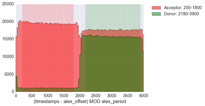
Alternation histogram showing selection for the donor and acceptor periods.
2.9.5. Measurement type
Each measurement_type has an associated set of mandatory fields which must be present to ensure that all information needed to unambiguously interpret the data is present. For example, for a 2-color smFRET measurement, a software package creating a file should check that the association between detector ID (previously called pixel) and donor or acceptor channel is present.
The list of supported measurement types is reported in Measurement specs.
2.9.6. Nanotimes time direction
In typical TCSPC measurement the start and stop inputs are inverted, i.e. the start is triggered by the photon and the stop by the the laser sync. This allows to start TAC or TDC measurements only when a photon is detected and not after each laser sync pulse. However, due to this experimental configuration, the resulting raw TCSPC histogram looks inverted along the time axis, with the nanotimes of photons emitted shortly after a laser pulse being larger than the nanotimes of photons emitted much later.
By convention, the Photon-HDF5 format requires nanotimes to be properly oriented.
In other words, when a /photon_data/nanotimes time axis inversion is needed,
this correction needs to be performed before the data is saved into a Photon-HDF5 file.
As a corollary, TCSPC histograms computed directly from nanotimes from Photon-HDF5
files are always properly oriented, regardless of the way the nanotimes were acquired.
2.9.7. Group /setup/detectors/
This group is new in version 0.5 and contains fields which are arrays, one
element per detector ID (both photon and non-photon) (see definition).
The only mandatory field is id which contains
all detectors IDs as they appear in /photon_data/detectors.
Within each spot, IDs appear in /setup/detectors/id in increasing order.
All values which appears in /photon_data/detectors need to be listed here.
Note that while v0.5 now has soft-support for non-photon IDs, supporting such events
as markers for FLIM, sync signals from the TCSPC card, signals for monitoring laser
power etc. overflow markers such as those present in many Picoquant formats must
be removed.
In TCSPC measurements where each detector (pixel) has different TCSPC bin width,
the /setup/detectors group allows to save per-photon detector TCSPC info.
In this case the the
nanotimes_specs group is not present in photon_data and the group
/setup/detectors will contain per-photon detector TCSPC info:
/setup/detectors/tcspc_units
/setup/detectors/tcspc_num_bins
2.9.8. Multi-spot measurements
Multi-spot measurements are simply handled by having multiple photon_data
groups, one for each excitation spot. The naming convention is the following:
photon_data0
photon_data1
...
photon_data10
...
photon_data100
Note that the enumeration starts from zero and there is no zero filling.
Each photon_dataN group will have a complete measurement_specs
sub-group so that it can effectively treated as a single-spot measurements
when reading the file.
As a result, even if the measurement_type field is not expected to change
for different spots, it will be replicated inside each photon_dataN
group.
In version 0.5 and above the /photon_dataNN/detectors arrays need to
contain detectors identifier which are unique across all the spots. In version
0.4 the same identifiers (e.g. 0 and 1) were allowed in different spots.