2. Photon-HDF5 format definition
2.1. Overview
A Photon-HDF5 is a HDF5 file with a predefined structure for timestamp-based data.
A screen-shot of a typical Photon-HDF5 file opened in HDFView is shown here:
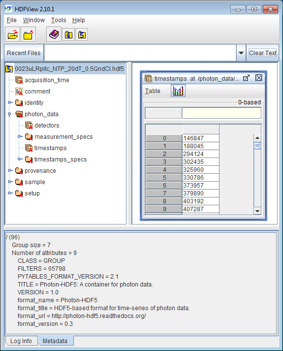
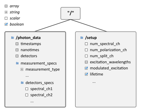
The previous figure shows the 5 main groups contained in a Photon-HDF5 file. Of these, /photon_data and /setup contains the raw data and all the information needed for the analysis. A schematic overview is shown in the next figure:
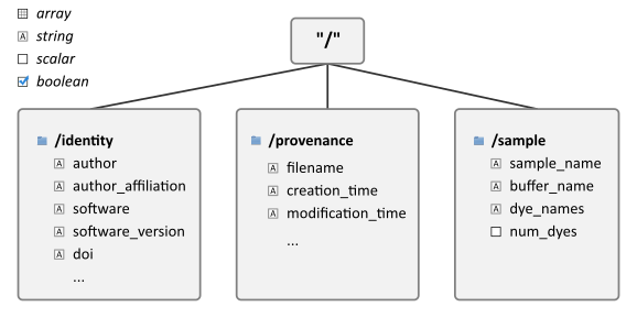
The remaining 3 groups (/sample, /identity, /provenance) provides
additional metadata that make the Photon-HDF5 files self-contained and
suitable long-term on-line archival. An overview of there groups is shown below:
As a quick reference, here we list links to the documentation for each group:
- /photon_data: RAW data and measurement type specifications.
- /setup: Description of the experimental setup.
- /identity: Information about the data file.
- /provenance: Information about the original data file (when the Photon-HDF5 file has been converted from another format).
- /sample: Description of the measured sample.
The following sections describe the Photon-HDF5 groups and fields.
2.2. Root-level parameters
The root node (“/”) in a Photon-HDF5 file contains the following fields:
- /acquisition_time: (float) the measurement duration in seconds.
- /comment: (string) a user-defined comment.
In addition, the root node has the following attributes that can be used to distinguish Photon-HDF5 files from other HDF5 files:
- format_name: must contain the string “Photon-HDF5”
- format_version: (string) the Photon-HDF5 format version.
2.3. Photon-data group
This section describes the layout and fields in the /photon_data group. Note that only the kind of data is specified (i.e. scalar, integer array, float array), but no data type size is mandated. For arrays, the most commonly used data-type is indicated.
Mandatory fields:
timestamps: (array) photon timestamps. Typical data-type int64.
- timestamps_specs/
- timestamps_unit: (float) timestamp units in seconds.
Optional if there is only 1 detector, otherwise mandatory:
- detectors: (array of integers) detector ID for each timestamp. Typical data-type uint8.
When the dataset contains nanotime information (i.e. arrival time of each photon with respect to a laser pulse), the following fields must be present:
nanotimes:(array of integers) TCSPC nanotimes. Typical data-type uint16.
- nanotimes_specs/
- tcspc_unit: (float) TAC/TDC bin size (in seconds).
- tcspc_range:(float) full-scale range of the TAC/TDC (in seconds).
- tcspc_num_bins: (integer) number of TAC/TDC bins.
- time_reversed: (boolean) True if nanotimes contains the time elapsed between a photon and the next laser pulse. False if it contains the time elapsed between a laser pulse and a photon.
Finally, if the data come from a simulation, /photon_data may contain:
- particles: (array of integers) a particle ID (integer) for each timestamp. Typical data-type uint8.
2.3.1. Measurement specs
The optional /photon_data/measurement_specs group contains additional information allowing unambiguous interpretation of the data for each specific type of measurement.
measurement_type: (string) the type of the measurements. Valid names are:
- “smFRET” (1 excitation color, 2 detection colors)
- “smFRET-usALEX” (2 excitation colors, 2 detection colors)
- “smFRET-usALEX-3c” (3 excitation colors, 3 detection colors)
- “smFRET-nsALEX” (2 excitation colors, 2 detection colors)
New names can be created for different kind of measurements and we encourage users to submit new name requests.
The measurement_type field describes the type of measurement saved within the file. It is an important field allowing software packages reading and saving Photon-HDF5 files to perform consistency checks (see also Measurement type).
For μs-ALEX, 2, 3 or N colors:
- alex_period: (integer or float) duration of one complete excitation
alternation period expressed in timestamp units. The alternation period
is equal to
alex_period * timestamps_unit.
For ns-ALEX (or lifetime with no alternation):
- laser_pulse_rate: (float) excitation laser pulse repetition rate in Hertz.
For 2-color (or more) μs-ALEX and ns-ALEX (optional):
- alex_period_spectral_ch1: (array with an even-number of integer elements) start and stop values identifying the spectral_ch1 (i.e. donor for smFRET measurements) emission period (see note below for more details).
- alex_period_spectral_ch2: (array with an even-number of integer elements) start and stop values identifying the spectral_ch2 (i.e. acceptor for smFRET measurements) emission period (see note below for more details).
- etc...
Note
For μs-ALEX, both alex_period_spectral_ch1 and alex_period_spectral_ch2 are 2-element arrays. In this case, these values are expressed in timestamps_units. For ns-ALEX (also known as PIE), they are arrays with an even-number of elements, comprising as many start-stop nanotime pairs as there are excitation periods within the TAC/TDC range. In this case these values are expressed in nanotimes_units.
For more details see Definition of alternation periods.
2.3.1.1. Detectors specs
Within measurement_specs, the detectors_specs/ sub-group contains all the detector ID–detection channel associations, i.e. spectral bands, polarizations or beam-split channels.
When a measurement records more than 1 spectral band, the fields:
- spectral_ch1
- spectral_ch2
- etc...
specify which detector is employed in each spectral band. When the measurement
records only 1 spectral band these fields may be omitted. The spectral bands
are strictly ordered for increasing wavelengths. For example, for 2-color
smFRET measurements spectral_ch1 and spectral_ch2 represent the
donor and acceptor channel respectively.
If a measurement records more than 1 polarization states, the fields:
- polarization_ch1
- polarization_ch2
specify which detector is used for each polarization. When the measurement records only one polarization, these fields may be omitted.
When the detection light is split into 2 channels using a non-polarizing beam-splitter the fields:
- split_ch1
- split_ch2
specify which detector is used in each of the “beam-split” channels.
All previous fields are arrays containing one or more detector IDs.
For example, a 2-color smFRET measurement will have only one value in
spectral_ch1 (donor) and one value in spectral_ch2
(acceptor). A 2-color smFRET measurement with polarization
(4 detectors) will have 2 values in each of the spectral_chX and
polarization_chX fields (where X=1 or 2).
For a multispot smFRET measurement, spectral_chX will contain the list
of donor/acceptor detectors (see Multi-spot measurements).
Finally, a label (string) can be associated to each detector using the optional labels field:
- labels: (optional) table with 2 columns: detector ID (integer) and detector label (string).
For 2-color smFRET measurements, it is recommended to use the “donor”
and “acceptor” labels for the respective detectors. Note, however, that these
labels only represent an additional user-defined metadata and are not
necessary for the interpretation of the measurement.
When detector ID is a n-tuple, labels has n+1 columns
(n for the ID and 1 for the labels).
2.4. Setup group
The /setup group contains information about the measurement setup:
- num_pixels: (integer) total number of detector pixels. For example, for a single-spot 2-color smFRET measurement using 2 single-pixel SPADs as detectors this field is 2.
- num_spots: (integer) the number of excitation (or detection) “spots” in the sample. This field is 1 for all the measurements using a single confocal excitation volume. When not applicable, for example under widefield illumination with 2-D imaging detectors, this field is omitted.
- num_spectral_ch: (integer) number of distinct detection spectral channels. For example, in a 2-color smFRET experiment there are 2 detection spectral channels (donor and acceptor), therefore its value is 2. When there is a single detection channel or all channels detect the same spectral band, its value is 1.
- num_polarization_ch: (integer) number of distinct detection polarization channels. For example, in polarization anisotropy measurements, its value is 2. When there is a single detection channel or all channels detect the same polarization (including when no polarization selection is performed) its value is 1.
- num_split_ch: (integer) number of distinct detection channels detecting the same spectral band and polarization state. For example, when a non-polarizing beam-splitter is employed in the detection path, its value is 2. When no splitting is performed, its value is 1.
- modulated_excitation: (boolean) True (or 1) if there is any form of excitation modulation either in the wavelength space (as in μs-ALEX or PAX) or in the polarization space. This field is also True for pulse-interleaved excitation (PIE) or ns-ALEX measurements.
- lifetime: (boolean) True (or 1) if the measurements includes a nanotimes array of (usually sub-ns resolution) photon arrival times with respect to a laser pulse (as in TCSPC measurements).
- excitation_wavelengths: (array of floats) list of excitation wavelengths (center wavelength if broad-band) in increasing order (unit: meter).
- excitation_cw: (array of booleans) for each excitation source,
this field indicates whether excitation is continuous wave (CW), True,
or pulsed, False.
The order of excitation sources is the same as that in
excitation_wavelengthsand is in increasing order of wavelengths.
The following fields are optional and not necessarily relevant for all experiments. If the associated information is irrelevant or not available, these fields are omitted.
- excitation_polarizations: (arrays of floats) list of polarization
angles (in degrees) for each excitation source.
The order of excitation sources is the same as in
excitation_wavelengthsand is in increasing order of wavelengths. - excitation_input_powers: (array of floats) excitation power in Watts for each excitation source. This is the excitation power entering the optical system.
- excitation_intensity: (array of floats) excitation intensity in the sample for each excitation source (units: Watts/meters²). In the case of confocal excitation this is the peak PSF intensity.
- detection_wavelengths: (arrays of floats) reference wavelengths (in
meters) for each detection spectral band.
This array is ordered in increasing order of wavelengths.
The first element refers to
detectors_specs/spectral_ch1, the second todetectors_specs/spectral_ch2and so on. - detection_polarizations: (arrays of floats) polarization angles
for each detection polarization band.
The first element refers to
detectors_specs/polarization_ch1, the second todetectors_specs/polarization_ch2and so on. This field is not relevant if no polarization selection is performed. - detection_split_ch_ratios: (array of floats) power fraction detected
by each “beam-split” channel (i.e. independent detection channels
obtained through a non-polarizing beam splitter). For 2 beam-split
channels that receive the same power this array should be
[0.5, 0.5]. The first element refers todetectors_specs/split_ch1, the second todetectors_specs/split_ch2and so on. This field is not relevant when no polarization- and spectral-insensitive splitting is performed.
2.5. Identity group
The identity/ group contains information about the specific Photon-HDF5 file. If some information is not available the relative field may be omitted.
- author: (string) the author of the measurement (or simulation).
- author_affiliation: (string) the company or institution the author is affiliated with.
- creator: (string) the Photon-HDF5 file creator. Used when the data was previously stored in another format and the conversion is performed by a different person than the author.
- creator_affiliation: (string) the company or institution the creator is affiliated with.
- url: (string) URL that allow to download the Photon-HDF5 data file.
- doi: (string) Digital Object Identifier (DOI) for the Photon-HDF5 data file.
- filename: (string) Photon-HDF5 file name at creation time. This field saves the original file name even if the file is later on renamed on disk.
- filename_full: (string) Photon-HDF5 file name (including the full path) at creation time.
- creation_time: (string) the Photon-HDF5 file creation time with the following format: “YYYY-MM-DD HH:MM:SS”.
- software: (string) name of the software used to create the Photon-HDF5 file.
- software_version: (string) version of the software used to create the Photon-HDF5 file.
- format_name: (string) this must always be “Photon-HDF5”
- format_version: (string) for the current version it must be “0.3”
- format_url: (string) A URL pointing to the Photon-HDF5 specification document.
2.6. Provenance group
The provenance/ group contains info about the original file that has been converted into a Photon-HDF5 file. If some information is not available the relative field may be omitted.
- filename: (string)
- filename_full: (string)
- creation_time: (string)
- modification_time: (string)
- software: (string)
- software_version: (string)
2.7. Sample group
The /sample group contains information related to the measured sample. This group is optional.
- num_dyes: (integer) number of different dyes present in the samples.
- dye_names: (array of string) list of dye names (for example:
['ATTO550', 'ATTO647N']) - buffer_name: (string) a user defined description for the buffer.
- sample_name: (string) a user defined description for the sample.
2.8. Additional notes and definitions
2.8.1. Detector IDs
A detector ID is the “name” of each pixels and is typically a single integer (when all the pixels are numbered with a progressive index). In some case (when using detector arrays) the detector ID can be a n-tuple of integers. This allow to specify, for each pixel, the module number and the X, Y location, for example. Therefore, an array of detector IDs can be either a 1-D column array or a 2-D array. In either cases, each row identifies a detector.
2.8.2. Beam-split channels
When the emitted light path is split in 2 or more detection paths by using a non-polarizing beam splitter the measurement has so called beam-split channels. The fields split_ch1 and split_ch2 contains the list of detector IDs for each beam-split channel (see Detectors specs).
2.8.3. Definition of alternation periods
2.8.3.1. Note for μs-ALEX
The alex_period_spectral_ch1 and alex_period_spectral_ch2 fields allow defining photons detected during donor or acceptor excitation. As an example, let’s define the array
A = timestamps MODULO alex_period
as the array of timestamps modulo the μs-ALEX alternation period. Photons emitted during the donor period (respectively, acceptor period) are obtained by applying one of these two conditions:
(A > start) and (A < stop)whenstart < stop(internal range)(A > start) or (A < stop)whenstart > stop(external range).
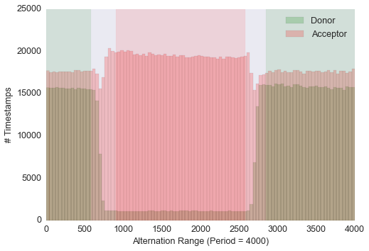
Alternation histogram showing selection for the donor and acceptor periods. In this case the donor period is defined as an “external range” (2850, 580) while the acceptor period is defined as an “internal range” (900, 2580). This situation is due to the ALEX period being out of phase with respect to the time stamping clock.
2.8.4. Measurement type
Each measurement_type has an associated set of mandatory fields which must be present to ensure that all information needed to unambiguously interpret the data is present. For example, for a 2-color smFRET measurement, a software package creating a file should check that the association between detector and donor or acceptor channel is present. If some necessary field is absent, the software package should warn the user in order that this information is added before saving the file.
2.8.5. Multi-spot measurements
Multi-spot measurements are simply handled by having multiple photon_data
groups, one for each excitation spot. The naming convention is the following:
photon_data0
photon_data1
...
photon_data10
...
photon_data100
Note that the enumeration starts from zero and there is no zero filling.